01
Start with intended use, not a generic equipment symbol
The same equipment label can hide different interfaces. A grossing station may be recirculating or connected to building exhaust; a tissue processor may require only electrical power or may also need drainage, remote alarms, and ventilation coordination; a slide scanner may add data bandwidth, heat, UPS, and service-access needs. Record the actual intended use and procurement status beside every item. Mark information as confirmed, provisional, or unknown so a planning assumption cannot silently become a construction instruction.
Review the list with pathologists, biomedical scientists, infection-prevention staff, occupational hygiene, facilities, information technology, equipment suppliers, and the design disciplines. WHO guidance frames laboratory design as a multidisciplinary, risk-based process, while NIH equipment-planning guidance recommends investigating dimensions, clearances, utilities, peripherals, heat, turbulence, and vibration early. The output should be a controlled equipment schedule linked to room data sheets and drawings, with an owner and review date for every unresolved interface.
02
Build one interface register that furniture and engineering teams can share
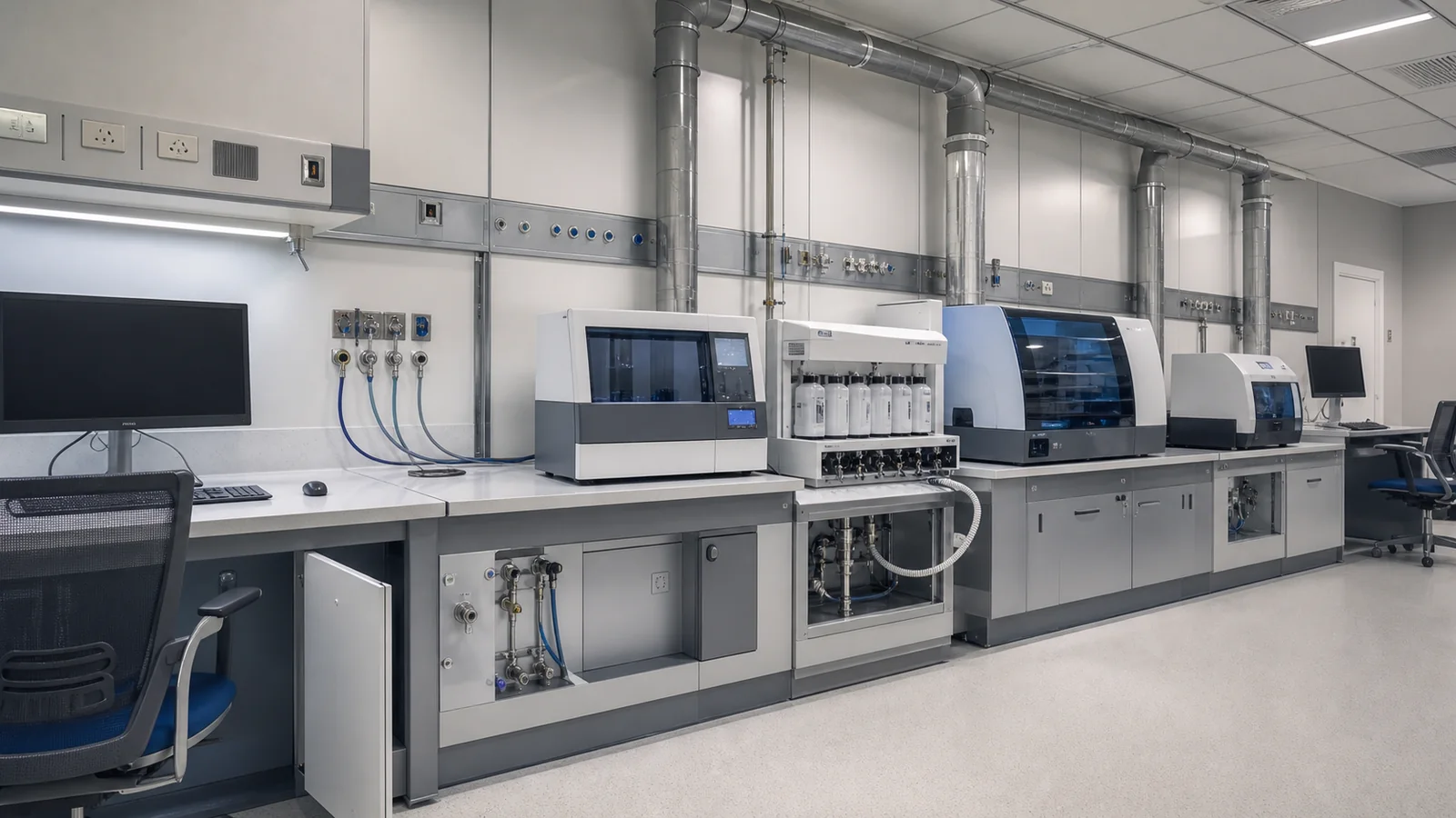
Give each equipment item a stable identifier and one row in the interface register. In addition to size and utility loads, capture operator position, sample loading side, consumable storage, waste removal, cleaning access, door swing, cable direction, under-bench or overhead services, and the manufacturer's maintenance envelope. A plan view alone is insufficient: elevations and sections are often needed to find collisions between a raised rear service zone, shelves, taps, splashbacks, duct transitions, monitor arms, and removable panels.
Link the register to furniture modules without assuming the furniture supplies every service. Distinguish the point provided by the building, the connection provided with the bench or enclosure, and the final connection required by the equipment supplier. Record who furnishes, installs, tests, labels, and accepts each element. This boundary is especially important for hard-connected units, remote pumps, chillers, extraction devices, alarm contacts, and components concealed behind cabinets, because later access must remain possible without dismantling the whole workstation.
03
Coordinate containment, exhaust, room air, and chemical work together
Pathology activities may involve fresh human material, formaldehyde solutions, processing reagents, stains, and cleaning chemicals, but the required control is determined by the task and assessed risk. CDC and WHO publications emphasize risk-based selection and correct use of containment. A biological safety cabinet, chemical fume hood, ventilated grossing station, local capture device, or enclosed instrument serves a particular purpose; one should not be substituted for another merely because both have fans. Confirm the device type before defining exhaust, make-up air, alarms, discharge, and room-pressure relationships.
Air distribution must also be checked around the equipment. Supply diffusers, doors, busy circulation, adjacent capture devices, and heat-producing instruments can affect the working environment or disturb sensitive containment. Formaldehyde is subject to occupational-exposure controls in jurisdictions applying the OSHA standard, including exposure assessment and engineering or work-practice decisions. The project team should therefore coordinate chemical inventory, operating procedure, local monitoring strategy, hood or capture selection, and maintenance access rather than treating an exhaust collar as the complete solution.
04
Resolve power, data, water, drainage, heat, and vibration as a system
An electrical schedule should separate ordinary power, emergency supply, UPS-backed circuits, hard-wired isolators, plug configurations, and restart behaviour after an outage. Data coordination should identify network outlets, instrument middleware, barcode devices, printers, remote alarms, clocks, and cybersecurity responsibilities without publishing sensitive network details. Check receptacle and data positions against real equipment cables and movable parts; an outlet shown behind a fixed plinth or inside a maintenance zone may be technically present but operationally unusable.
For water and drainage, record quality, temperature, pressure, flow, trap and vent needs, permitted discharge, condensate, leak detection, and access for isolation and cleaning. Do not infer these values from a similar model. Add room heat release, noise, floor loading, anchorage, and vibration sensitivity to the same review. NIH guidance notes that heat-producing and turbulence-sensitive equipment must be coordinated with air distribution, while vibration-producing and vibration-sensitive devices may need separation or isolation. Supplier data and project engineering determine the final response.
05
Use procurement gates and commissioning checks to control change
Establish coordination gates before tender, before construction release, after supplier submittal, before factory or site installation, and before commissioning. At each gate, compare the current equipment register with architectural, furniture, mechanical, electrical, plumbing, fire, structural, and information-technology drawings. A changed model number should trigger an interface review rather than a simple schedule edit. Photograph concealed services before closure and keep approved connection details with asset records for future maintenance and replacement.
Site verification should confirm delivery clearances, finished openings, levels, service locations, isolation labels, maintenance space, drainage falls where applicable, and safe access before equipment arrives. Commissioning responsibilities should identify who starts the device, tests connected services and alarms, records baseline conditions, trains users, and closes defects. This process does not certify clinical performance or regulatory acceptance; it creates traceable evidence that the physical interfaces were reviewed and gives the hospital a clearer basis for its own validation, safety, and operational approvals.