01
Begin with methods and equipment facts, not generic service points
Build the model from the tests the laboratory will perform. Map receipt, conditioning, preparation, measurement, review, retention, cleaning, and waste transfer. Give every instrument and peripheral a unique ID linked to its method, sample condition, operator, consumables, and controls. NIST's fasteners and metals handbook shows why physical setup matters: assessment can examine facilities, equipment, preparation, calibration, test conditions, and records together. A room name cannot define those conditions.
Record whether each model is approved, provisional, existing, or planned, and attach the current manufacturer document. Treat the instrument, autosampler, computer, pump, chiller, gas treatment, waste vessel, and extraction accessory as one system. This exposes peripherals that block cabinetry, need separate power, reject heat, or require maintenance access. Keep unresolved values visible with an owner and decision date rather than filling the schedule with assumptions.
02
Coordinate the operating and service envelope with the workstation
A workable station includes delivery, operation, calibration, and repair space. Capture dimensions, mass, point loads, moving doors, loading direction, hose bend radii, ventilation clearance, operator reach, and component replacement routes. Agilent's GC guide separates clearance, heat, exhaust, power, gas, and network needs. Thermo Fisher's ICP-MS guide reserves access around gas, power, exhaust, vacuum, computer, and emergency shutoff connections. These are model-specific inputs, not reusable brand-neutral dimensions.
Translate those envelopes into coordinated elevations and sections before furniture release. Confirm bench depth, support and vibration criteria, knee space, rear service zones, access panels, cut-outs, spill management, and wet-work separation. Keep valves, outlets, regulators, pump controls, and emergency switches reachable without dismantling fixed furniture. Review delivery doors, lifts, corners, temporary protection, lifting methods, and final positioning at the same time; a suitable operating location is irrelevant if the system cannot reach it safely.
03
Use one point-to-point matrix for every utility interface
Create one row for every connection: power, earthing, data, gas, vacuum, cooling or purified water, drain, solvent waste, instrument or heat exhaust, alarm, and interlock. Record the manufacturer requirement, units, connection point, routing, isolation, material or cleanliness need, verified pressure or flow basis, and responsibility for supply, connection, testing, labelling, and records. An outlet symbol does not prove that capacity, quality, protection, and location are correct.
Water connections need deliberate engineering. SLAC notes that improvised hose-barb, tubing, and clamp arrangements can fail when pressure, stress, or wear changes. Use reviewed connections with rated components, suitable isolation, restrained routing, inspection access, and any justified leak response. Apply the same discipline to gases and waste: define source, regulator, purity, compatible tubing, termination, ventilation dependency, changeover access, and who verifies the completed line before use.
04
Treat exhaust and room conditions as part of measurement infrastructure
Separate room ventilation, local capture, instrument exhaust, pump exhaust, and heat removal. General air change does not prove source capture, and an extraction arm does not suit every emission. Stanford identifies local exhaust connections for equipment such as gas chromatographs and vacuum pumps when hazardous pollutants may be produced. Evaluate the substance, source geometry, temperature, operating state, discharge route, monitoring, and failure response before selecting a device that also preserves equipment access and room airflow.
Temperature, humidity, drafts, corrosive atmosphere, dust, vibration, electromagnetic influence, and heat rejection may affect results. Set limits from the approved method and current manufacturer documents, place representative sensors, and define recording and response. Test the room and local interfaces under realistic loads, including simultaneous operation where applicable. An installed duct or energized socket is only a construction milestone; commissioning must confirm operating conditions and document restrictions rather than turning assumptions into acceptance.
05
Verify interfaces in stages and control every late change
Plan verification before procurement. At design release, review the equipment register, drawings, utility matrix, manufacturer documents, and responsibilities. Inspect concealed routes before closure. Before delivery, confirm access, bench readiness, connection locations, measured supplies, exhaust, environment, and waste arrangements. After connection, record tests, labels, set points, alarms, isolation, as-built information, training, and acceptance. Distinguish cosmetic defects from interfaces that prevent valid or safe operation.
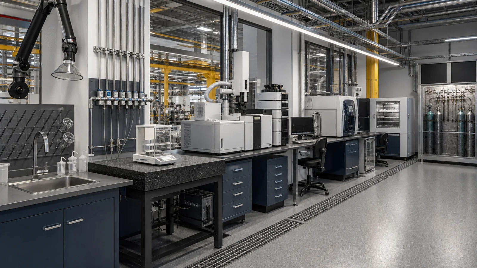
YOJIA's authorized anonymized industrial quality-testing case shows visible perimeter benches, instruments, a sink, storage, and local extraction. The photographs can prompt questions about reach, circulation, and service access; they do not prove hidden pipework, airflow, calibration, compliance, or measured performance. Use them with drawings and records, never instead of them. When a model, method, or room use changes, reopen affected matrix rows so furniture, utilities, exhaust, controls, and acceptance criteria change together.